Many “gears” are utilized for automobiles, but they are also utilized for many various other machines. The most typical one may be the “tranny” that conveys the energy of engine to tires. There are broadly two functions the transmission of a car plays : one can be to decelerate the high rotation velocity emitted by the engine to transmit to tires; the additional is to change the reduction ratio in accordance with the acceleration / deceleration or driving speed of an automobile.
The rotation speed of an automobile’s engine in the overall state of generating amounts to at least one 1,000 – 4,000 rotations each and every minute (17 – 67 per second). Since it is difficult to rotate tires with the same rotation velocity to perform, it is required to lessen the rotation speed using the ratio of the amount of gear teeth. This kind of a role is named deceleration; the ratio of the rotation swiftness of engine and that of wheels is named the reduction ratio.
Then, why is it necessary to change the reduction ratio relative to the acceleration / deceleration or driving speed ? The reason being substances need a large force to begin moving however they do not require this kind of a large force to excersice once they have started to move. Automobile could be cited as an example. An engine, nevertheless, by its character can’t so finely modify its output. Therefore, one adjusts its result by changing the decrease ratio utilizing a transmission.
The transmission of motive power through gears very much resembles the principle of leverage (a lever). The ratio of the number of tooth of gears meshing with one another can be considered as the ratio of the length of levers’ arms. That is, if the decrease ratio is huge and the rotation speed as output is low in comparison compared to that as insight, the power output by tranny (torque) will be large; if the rotation quickness as output isn’t so lower in comparison compared to that as insight, however, the energy output by transmitting (torque) will be small. Thus, to improve the decrease ratio utilizing transmitting is much comparable to the basic principle of moving things.
After that, how does a transmission alter the reduction ratio ? The answer lies in the mechanism called a planetary equipment mechanism.
A planetary gear system is a gear mechanism comprising 4 components, namely, sunlight gear A, several world gears B, internal gear C and carrier D that connects world gears as observed in the graph below. It includes a very complex framework rendering its design or production most difficult; it can understand the high reduction ratio through gears, however, it is a mechanism suited to a reduction system that requires both small size and powerful such as for example transmission for automobiles.
In a planetary gearbox, many teeth are involved at once, which allows high speed decrease to be achieved with relatively small gears and lower inertia reflected back to the engine. Having multiple teeth discuss the load also enables planetary gears to transmit high degrees of torque. The mixture of compact size, large speed reduction and high torque tranny makes planetary gearboxes a favorite choice for space-constrained applications.
But planetary gearboxes perform have some disadvantages. Their complexity in design and manufacturing tends to make them a more expensive remedy than various other gearbox types. And precision production is extremely important for these gearboxes. If one planetary gear is positioned closer to the sun gear than the others, imbalances in the planetary gears may appear, resulting in premature wear and failing. Also, the compact footprint of planetary gears makes high temperature dissipation more difficult, therefore applications that operate at very high speed or experience continuous procedure may require cooling.
When using a “standard” (i.electronic. inline) planetary gearbox, the motor and the powered equipment must be inline with each other, although manufacturers provide right-angle designs that include other gear sets (often bevel gears with helical the teeth) to provide an offset between the input and output.
Input power (max)27 kW (36 hp)
Input speed (max)2800 rpm2
Output torque (intermittent)12,880 Nm(9,500 lb-ft)
Output torque (continuous)8,135 Nm (6,000 lb-ft)
1 Actual ratio is dependent on the drive configuration.
2 Max input speed related to ratio and max result speed
3 Max radial load positioned at optimum load position
4 Weight varies with configuration and ratio selected
5 Requires tapered roller planet bearings (not available with all ratios)
Approximate dry weight100 -181 kg (220 – 400 lb)4
Radial load (max)14,287kg (31,500 lb)3
Drive typeSpeed reducer
Hydraulic engine input SAE C or D hydraulic
Precision Planetary Reducers
This standard selection of Precision Planetary Reducers are perfect for use in applications that demand powerful, precise positioning and repeatability. They were specifically developed for make use of with state-of-the-art servo electric motor technology, providing limited integration of the motor to the unit. Design features include installation any servo motors, standard low backlash, high torsional stiffness, 95 to 97% efficiency and silent running.
They can be purchased in nine sizes with reduction ratios from 3:1 to 600:1 and result torque capacities up to 16,227 lb.ft. The output could be provided with a good shaft or ISO 9409-1 flange, for installation to rotary or indexing tables, pinion gears, pulleys or other drive components without the need for a coupling. For high precision applications, backlash amounts right down to 1 arc-minute can be found. Right-angle and input shaft versions of the reducers are also obtainable.
Regular applications for these reducers include precision rotary axis drives, traveling gantries & columns, material handling axis drives and digital line shafting. Industries offered include Material Managing, Automation, Aerospace, Machine Tool and Robotics.
Unit Design &
Construction
Gearing: Featuring case-hardened & floor gearing with minimal wear, low backlash and low noise, making them the the majority of accurate and efficient planetaries obtainable. Standard planetary design has three planet gears, with a higher torque version using four planets also offered, please see the Reducers with Result Flange chart on the Unit Ratings tab under the “+” unit sizes.
Bearings: Optional output bearing configurations for software particular radial load, axial load and tilting moment reinforcement. Oversized tapered roller bearings are regular for the ISO 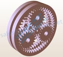 Flanged Reducers.
Housing: Single piece metal housing with integral ring gear provides greater concentricity and remove speed fluctuations. The housing can be fitted with a ventilation module to improve insight speeds and lower operational temperatures.
Output: Available in a solid shaft with optional keyway or an ISO 9409-1 flanged interface. You can expect an array of standard pinions to install right to the output style of your choice.
Unit Selection
These reducers are typically selected based on the peak cycle forces, which usually happen during accelerations and decelerations. These cycle forces rely on the driven load, the rate vs. time profile for the routine, and any other exterior forces acting on the axis.
For application & selection assistance, please call, fax or email us. Your application details will be examined by our engineers, who’ll recommend the very best solution for your application.
Ever-Power Automation’s Gearbox products offer high precision in affordable prices! The Planetary Gearbox item offering contains both In-Line and Right-Angle configurations, built with the design goal of supplying a cost-effective gearbox, without sacrificing quality. These Planetary Gearboxes can be found in sizes from 40mm to 180mm, perfect for motors which range from NEMA 17 to NEMA 42 and bigger. The Spur Gearbox line provides an efficient, cost-effective choice appropriate for Ever-Power Automation’s AC Induction Gear Motors. Ever-Power Automation’s Gearboxes can be found in up to 30 different equipment ratios, with torque rankings up to 10,488 Planetary Gear Reduction in-lbs (167,808 oz-in), and are compatible with most Servo,
SureGear Planetary Gearboxes for Small Ever-Power Motors
The SureGear PGCN series is an excellent gearbox value for servo, stepper, and other motion control applications requiring a NEMA size input/output interface. It includes the best quality designed for the price point.
Features
Wide variety of ratios (5, 10, 25, 50, and 100:1)
Low backlash of 30 arc-min or less
20,000 hour service life
Free of maintenance; requires no additional lubrication
NEMA sizes 17, 23, and 34
Includes hardware for mounting to SureStep stepper motors
Optional shaft bushings available for mounting to other motors
1-year warranty
Applications
Material handling
Pick and place
Automation
Packaging
Other motion control applications requiring a Ever-Power input/output
Spur gears certainly are a type of cylindrical equipment, with shafts that are parallel and coplanar, and tooth that are directly and oriented parallel to the shafts. They’re arguably the easiest and most common kind of gear – simple to manufacture and ideal for a range of applications.
One’s the teeth of a spur gear have got an involute profile and mesh 1 tooth simultaneously. The involute type means that spur gears just generate radial forces (no axial forces), nevertheless the approach to tooth meshing causes ruthless on the gear the teeth and high sound creation. For this reason, spur gears are often utilized for lower swiftness applications, although they could be utilized at almost every speed.
An involute tools tooth includes a profile this is actually the involute of a circle, which means that since two gears mesh, they get in touch with at an individual point where in fact the involutes fulfill. This aspect actions along the tooth areas as the gears rotate, and the kind of force ( referred to as the line of actions ) can be tangent to both foundation circles. Hence, the gears stick to the essential regulation of gearing, which promises that the ratio of the gears’ angular velocities must stay continuous throughout the mesh.
Spur gears could be produced from metals such as for example steel or brass, or from plastics such as nylon or polycarbonate. Gears produced from plastic produce much less audio, but at the difficulty of power and loading capability. Unlike other devices types, spur gears don’t encounter high losses because of slippage, therefore they often times have high transmission functionality. Multiple spur gears can be employed in series ( referred to as a equipment teach ) to attain large reduction ratios.
There are two primary types of spur gears: external and internal. Exterior gears have got the teeth that are cut externally surface area of the cylinder. Two exterior gears mesh with one another and rotate in opposite directions. Internal gears, on the other hand, have the teeth that are cut inside surface of the cylinder. An exterior gear sits in the internal equipment, and the gears rotate in the same path. Because the shafts are positioned closer together, internal gear assemblies are more compact than external gear assemblies. Internal gears are primarily used for planetary gear drives.
Spur gears are generally viewed as best for applications that require speed decrease and torque multiplication, such as for example ball mills and crushing equipment. Examples of high- velocity applications that make use of spur gears – despite their high noise levels – include consumer appliances such as washing machines and blenders. And while noise limits the use of spur gears in passenger automobiles, they are generally found in aircraft engines, trains, and even bicycles.